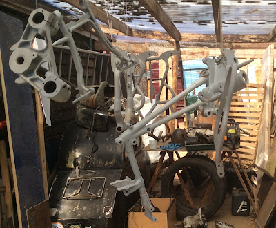
First though, headstock transfers. With the front frame stood upright on the floor the headstock transfers were applied. I used waterslide transfers as I already had the top one and I bought the lower one from Classic Transfers who are slightly cheaper than the VMCC transfer scheme. The top one has white panels unlike the original varnish-on type where these are clear allowing the paint below to show through. Waterslide are much easier to apply and are varnished over when dry. (Don't use cellulose based varnishes which will destroy the transfers.)
 |
| Headstock transfers. |
 |
| First parts laid on the table. |
The engine plates, bearing bracket and stand were loosely assembled with the greased sleeve nuts and central stud.
 |
| Engine plates, bearing block, stand and gearbox in place. |
The small scissor table shown lifted the assembly and with the stand down made a stable platform. With all the fixings loose and the right hand 7/16" bolt below the gearbox omitted the right hand engine plate can be swung down and the gearbox inserted and held in place by the top stud before replacing the bolt underneath. With the bottom gearbox stud in place the top one was taken out. The front frame was then put between the engine plates and the bottom 3/8" frame stud inserted. The frame was then swung up until the holes aligned at the top of the gearbox when the 1/2" top gearbox stud was inserted loosely. The second 3/8" stud at the bottom of the front frame was then slid into place.
 |
| Spacer on gearbox top mount |
In addition there is always a gap between the right hand battery lug on the front frame and the right hand ear of the bearing bracket. Again this will vary between frames and should be measured with feeler gauges and a spacer made to suit and inserted. In this case the top mount of the gearbox needed a washer 0.06" thick. A washer 0.11" thick was fitted between the two frame parts and the stud nipped up.
 |
| Spacer between frame lug and bearing bracket. |
The two spacers to the bottom mounting, 5/8" on the left side and 1.125" on the right slid snugly into place suggesting the gearbox is in the right place. Only time will tell as chain alignment is fixed by the engine sprocket as its taper fit is not adjustable sideways.
 |
| Front and rear frames added. Sharp eyes will notice that the stand is in the wrong way round. |
The rear subframe was added and bolted at the top to the front frame and at the bottom to the stand sleeve nuts. It was then noticed that the stand was in backwards. This is easily corrected at this stage by removing the bottom bolts and hinging the rear frame up whereupon the stand nuts can be removed, the stand reversed, and everything bolted up again. This took about five minutes.
 |
| Stand corrected. |
 |
| Swinging arm installed. |
 |
| Rear Shock Absorber Parts. |
The rear shocks were put together using the old parts painted and plated. The springs were ok but lightly rusted so were cleaned up and greased. All the rubber mounting buffers were perished so were replaced and new stainless inner tubes made. The replacement rubbers are Mini front suspension bushes, that is for a proper Mini, not the modern 'Volkswagen' replacement.
I have now run out of painted parts so need to get back into the spray booth and I also want to sort out the mysteries of the front forks.


