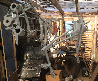
Tuesday, 30 July 2019

The Tinware

     As I've mentioned before the tinware, that is mudguards, headlamp, rear chainguard, toolboxes and fuel tank, was in a fairly poor state. The front mudguard was a non-Panther guard, holed with rust and chopped up when we loaded the van. The rear mudguard was a deeply valanced Panther type but upon dismantling it turned out to be a Panther front guard with a rusty extension bolted on to make up the length. The rear chainguard was the correct one although it had been repaired with the lower section replaced and fixed with pop-rivets. I decided to reuse this as is, just clean and paint. The toolboxes had both lost their lower third to the rust worm and were put to one side for later consideration. The headlamp was rusty on its lower half but recoverable, the fuel tank was beyond salvation. The rear number plate and the seat pan were both rusty and a little moth-eaten but usable.

Remains of the front guard.

Rear mudguard as taken off.


The fuel tank beyond repair


Seat, foam, pan and cover
       The mudguards were stripped of paint and the numerous drilled holes and the odd rusted thin area were welded up and filled. The replacement back mudguard from my shed appears to be from a BSA as it had a recess at the bottom for the swinging arm. This was dressed out (for which read hit with a large hammer!) All the parts were rubbed down, sprayed with a primer filler then a couple of coats of top coat. I used a cutting compound and polish on this for a decent finish but went through to the primer on the rear mudguard so had to start again on that. Finish is not concours but looks adequate to me so the parts were bolted to the frame.
 
Front mudguard and headlamp shell.

Rear mudguard, number plate and chainguard.

Seat pan.
     The replacement fuel tank is on its way and there is still work to do on the toolboxes but I shall turn to the engine next after a longish break during which I hope to lace up some wheels..

Saturday, 13 July 2019

The Mysterious Trail.

     This Panther came with a set of leading link forks which look to be home made as the welding is pretty lumpy. This type of fork has been likened to fitting power steering to a motorcycle combination. Unfortunately in this case the pivot blocks on the leading link arm had completely rusted away so I had no idea where they should be. This meant a little research into the arcane laws of TRAIL.
     The contact point of the front wheel of a motorcycle should trail behind the steering axis where it meets the ground to give a castor action. That is the wheel will return naturally to the straight ahead position after a turn, thus a bicycle can be ridden 'hands off' due to the trail of the wheel. This is positive trail, a lot of which makes for a stable machine at high speed but a sluggish one at low speed. Negative trail with the tyre contact in front of the steering axis leads to an unstable and very dangerous machine as the wheel wants to return to positive trail. Try pushing a bike backwards 'hands off.
 
Trail for the late Panther fork (Dimensions are approximate.)
     
      On a motorcycle combination a lot of trail makes for very heavy steering giving a tiring ride with a lot of hard work so the trail should be reduced but remain positive. The front wheel needs to be moved forwards to reduce trail and backwards to increase it. P&M did this on their own forks and on Dowty forks by offsetting the axle from the centreline of the stanchion. Reversing the fork would change the trail but to a fairly minimal degree. I've ridden Panthers solo with the trail set in both positions, it seems to make little difference. Note that with late Panther forks you need to change the sliders to the other side so for solo use the brake is on the left hand side of the machine. Generally the bikes left the factory set for sidecar trail.

      I set about measuring the trail on my bikes, not easy when it's all together. The late heavyweight Panther fork gives trails of 3.7" sidecar and 5.1" solo, Dowty forks, 2.2" and 3". My Douglas Dragonfly and Panther 10/3 have Earles forks, a form of leading link, with solo trail only 4" and 3.5" respectively. All measurements are approximate. Apparently Harleys have trail of 6"! The old bible 'Motorcycles and how to manage them,' suggests a positive trail of 1.5 inches for a sidecar outfit so I intend to aim for that but provide several mounting points to give an option for solo use. Drillings are provided for trails of 1.5”, 3” and 4”.
 
Setting out of leading links (Dimensions approximate.)


      First I assembled the headstock bearings and fitted the yokes to the frame. The compound, braced, fork leg pair was put into the yokes, a tricky job as both legs have to go in together. I used two lengths of studding, nuts and washers to draw them into place. I put the rear wheel and a shock absorber into the swinging arm temporarily and adjusted the scissor table to give the correct ride height at the front using a dimension obtained from my M120.
      A length of steel rod was passed through the crown nut and down the headstock stem to touch the bench. It was centralised in the bottom yoke by a drilled wine cork, (of course the wine had to be drunk first!) This gave the position of the steering axis at road level and the bench was marked accordingly.


Steel rod giving steering axis.
       I fitted the original front shocks fully extended to their lugs and jacked the leading link up to contact my new saddles. This gave the original setting out more or less and gave a trail of about 2.5 inches. To move the wheel forward to a trail of 1.5 inches I had to disconnect the shocks to avoid the angle of the link changing. For solo trail the wheel is moved backwards so that the shocks are then too long when fitted between the welded lugs.

Original set up. approximate. (Saddles not fixed at this stage.)

       My main concern, apart from whether the bike handles ok or not, is that in the maximum trail position the back of the link may foul the exhaust pipe. I've taken a check dimension of my other heavyweight and it is going to be tight.
        The prepared saddles and bolts were tacked in position to the link and the whole assembly was fitted to the fork legs to check the setting out before they were fully welded in place. The welding was done professionally as I don't trust my own; a failure here is not to be contemplated.
 
Saddles located and tacked in place.
       As mentioned  above this setting out is different to that originally fitted so the shock absorbers will not fit between the lugs provided; these are welded to the fork legs and the link. The top ones were cut off and some sidecar clamps were prepared with new bolts and shims to provide adjustable top fittings to the shocks. Time will tell if the trail is correct!


Upper clamp fittings

       The shocks were cleaned up and painted and the springs plated. the lower rubbers looked ok but the upper ones were replaced.

Front shocks cleaned up and plated.

         The fork was assembled using new stainless bolts and self-locking nuts. I have checked the fit of the mudguard and it is clear that the setting for maximum (solo) trail will need to have a different or modified mudguard, if indeed the rear of the fork will clear the exhaust pipe. I used the central hole for assembly as I shall run the bike solo at first while I prepare the sidecar chassis. The first ride could be quite interesting!

Final assembly, the red wheel is temporary.
Ready for a mudguard and wheel.
       Now I need to sort the tinware and the wheels.

Sunday, 23 June 2019

Frame assembly begins.

      With the major parts painted and the gearbox ready it was time to start assembling the frame.


      First though, headstock transfers. With the front frame stood upright on the floor the headstock transfers were applied. I used waterslide transfers as I already had the top one and I bought the lower one from Classic Transfers who are slightly cheaper than the VMCC transfer scheme. The top one has white panels unlike the original varnish-on type where these are clear allowing the paint below to show through. Waterslide are much easier to apply and are varnished over when dry. (Don't use cellulose based varnishes which will destroy the transfers.)
Headstock transfers.
First parts laid on the table.
      The engine plates, bearing bracket and stand were loosely assembled with the greased sleeve nuts and central stud.
Engine plates, bearing block, stand and gearbox in place.
      The small scissor table shown lifted the assembly and with the stand down made a stable platform. With all the fixings loose and the right hand 7/16" bolt below the gearbox omitted the right hand engine plate can be swung down and the gearbox inserted and held in place by the top stud before replacing the bolt underneath. With the bottom gearbox stud in place the top one was taken out. The front frame was then put between the engine plates and the bottom 3/8" frame stud inserted. The frame was then swung up until the holes aligned at the top of the gearbox when the 1/2" top gearbox stud was inserted loosely. The second 3/8" stud at the bottom of the front frame was then slid into place.
Spacer on gearbox top mount
       The top gearbox mounting should be a snug fit between the left hand ear of the bearing bracket and the right hand battery lug on the front frame. If there is slack here it should be measured with feeler gauges and a suitable spacing washer inserted as the frame is too stiff to be pulled in with the bolt.
      In addition there is always a gap between the right hand battery lug on the front frame and the right hand ear of the bearing bracket. Again this will vary between frames and should be measured with feeler gauges and a spacer made to suit and inserted. In this case the top mount of the gearbox needed a washer 0.06" thick.  A washer 0.11" thick was fitted between the two frame parts and the stud nipped up.

Spacer between frame lug and bearing bracket.

      The two spacers to the bottom mounting, 5/8" on the left side and 1.125" on the right slid snugly into place suggesting the gearbox is in the right place. Only time will tell as chain alignment is fixed by the engine sprocket as its taper fit is not adjustable sideways.


Front and rear frames added. Sharp eyes will notice that the stand is in the wrong way round.
      The rear subframe was added and bolted at the top to the front frame and at the bottom to the  stand sleeve nuts. It was then noticed that the stand was in backwards. This is easily corrected at this stage by removing the bottom bolts and hinging the rear frame up whereupon the stand nuts can be removed, the stand reversed, and everything bolted up again. This took about five minutes.


Stand corrected.
      The swinging arm was offered up and the greased pin inserted until the flats at the end engaged with the recess in the bearing bracket. This was tapped in tight with a soft mallet and the adjusting nut and lock nut added and tightened. checking that the swinging arm sits centrally between the rear frame. Everything seemed snug and the arm moved smoothly with no play.


Swinging arm installed.

Rear Shock Absorber  Parts.
      The rear shocks were put together using the old parts painted and plated. The springs were ok but lightly rusted so were cleaned up and greased. All the rubber mounting buffers were perished so were replaced and new stainless inner tubes made. The replacement rubbers are  Mini front suspension bushes, that is for a proper Mini, not the modern 'Volkswagen' replacement.

      I have now run out of painted parts so need to get back into the spray booth and I also want to sort out the mysteries of the front forks.

Wednesday, 12 June 2019

Slow progress, or maybe not!


All done? Well actually no, still a long way to go. This is my M120 and Panther chassis which I’ve had for probably 37 years but it’s something to aim for with the Wreck.

The major parts of the frame were rubbed down and any rusty areas treated with Kurust which allegedly converts and neutralises the rust. It was then hung up and given a couple of coats of primer followed by three coats of black cellulose, all sprayed on.


Spraybooth, the old greenhouse. (Note the sidecar.)
 
You cannot assemble the springer frame without having the gearbox to hand unless you want to take half of it apart again so I turned to that. In addition I was waiting for the plating to come back.
Externally the gearbox was white with alloy corrosion but dismantled easily. The internals were found to be in very good condition and just needed a quick clean. The corrosion on the cases came off easily using a rotating wire brush bolted to an old washing machine motor. This gave quite a nice shiny finish. As is common the threads for the chain adjusters on the bottom mounting were stripped so these were helicoiled to 5/16" BSF, a coarser thread than the original Cycle thread which is easily stripped.
The brush was also used on the rusty ends of the kickstart and gear change spindles. Reassembly was quite straightforward and it clicked cleanly into all gears when finished. I replaced the sprocket which was badly worn and fitted the short clutch pushrod which was missing. The gear lever is rotted through and went onto the scrap pile.


Gearbox parts


Kickstart case parts


Finished gearbox.
Finally the plating came back. Many of the parts, particularly the shrouds on the shock absorbers were quite deeply pitted and were unlikely to clean up sufficiently for chroming so everything was zinc plated and passivated. Some parts that were beyond saving were replaced from the boxes that litter my garage. It's very frustrating when you know you have something but can't find it anywhere.

Plated parts.
Anyway all parts are there for basic assembly of the frame.

Wednesday, 22 May 2019

The Engine


As I mentioned before, the engine has been open to the elements with the rocker cover off for many years. Even so it came apart without too much effort. Externally the cases are white with alloy corrosion and the cylinder and head are very rusty.
 
Externally the head has one broken fin and the exhaust threads are badly eroded. It was soaked in diesel and the inlet rocker removed. The exhaust rocker spindle is seized immovably in the rocker. The rocker is badly pitted and it would be unsafe to reuse it in its weakened state as even good ones are prone to break if the exhaust valve nips up. Another job for the angle grinder although you would need to be hard pressed to use a head in this condition.


The cylinder is rusty with some paint still adhering but  as it is cast iron the rust is not deep. The bore looks ok and came with a +40 slipper piston, the normal type of piston for a 1951 engine. The cylinder and piston could be reused.
 

The crankcase has clearly been full of water for a long time as there are tide marks on both halves and on the flywheels. The timing case was full of sludge and the half compression parts are rusted solid. The cam is a bit pitted although the timing gears look reusable. The pushrod tube appears to have a home-made lower half with the tappets running in a block pressed into the crankcase. Again this looks home-made.
Internals

The drive side crankcase is split across the front and down the side just above the row of bolts, presumably the result of water freezing in the crankcase. The flywheels and conrod are very rusty and the bigend is solid. The main bearings are a roller race on the timing side and two ball races on the drive side. This is the arrangement listed for a 1951 engine although in this case they are heavily rusted.
Timing case full of crud

Home-made tappet block

Drive side tide mark

Split drive side crankscase.
Rusty flywheels.
Bigend has seen better days.
            I do not plan to reuse this engine as there are too many parts such as the head and crankcase which are probably beyond repair. I have a 600 engine at the back of the shed which was running when it was replaced as it was using oil. I think this was because the conrod is slightly bent so I shall need to have a look at that.
            Out of interest I dismantled the big end, it took a two-leg puller to get it apart as it was solidly corroded.
Corroded conrod and big end.


Thursday, 9 May 2019

Dismantling and Assessment.

Now it’s time to examine the pile of bits more closely.

The Frame
The frame appears to be sound with light rusting here and there. I decided to strip the paint by hand using chemical paint stripper and wished I hadn’t, it’s slow, laborious and filthy. Better to find a shot blaster but you need to blank off the headstock and swing arm bearings to avoid filling with shot sand. The swing arm bearings appear to be ok with no play.

The wheels.
The wheel rims and spokes are completely rusted out on all four wheels so I have cut all the spokes and taken out the hubs. These are ok internally, externally they and the trim discs and brake plates, indeed all the alloy parts, are white with alloy corrosion. The front brake was seized in the hub but five weeks soaking in diesel and judicious tapping got the thing apart. The alloy parts need to be bead blasted. The brake shoes and linings appear to be ok.
Scrap wheel rims

Stripped hubs

The Front Forks
The front forks are not Panther but a leading link design which may be home made. Again the angle grinder was needed to get them apart.  The pivot for the swing arm is totally rusted away leaving the swing arm attached only by the shocks. The shocks  are also quite rusty and further investigation is needed to see if they can be disassembled.
Dismantled forks

The Tinware.
Most of the tinware is badly corroded. The petrol tank is scrap with large holes where the knee grips were and with the bottom virtually gone. One petrol tap fell out with a piece of tank attached. The badges and taps may be salvageable.

Petrol tank, beyond repair?

The front mudguard was non-Panther and rusted out. It was also cut in half as we tried to get the bike into the van. The rear mudguard turned out to be a Panther front mudguard with a short length attached to make it long enough. I have an original steel rear mudguard somewhere so can make up a pair.
The tool boxes are both rotted away at their lower extremities. Since they are identical and one is mounted on the bike upside down relative to the other it may be possible to cut and shut and make one from the two. Whether my skills are adequate for that is debatable.
Shredded tool boxes
The rear chainguard has been fitting with a steel plate but looks ok. Headlight is ok complete with speedo, ammeter and panther’s head badge, as is the rear number plate. The tail light is missing.

The Primary Drive
The primary chaincase is complete but white with corrosion. The complete clutch was found in the sidecar boot and is fairly rusted. It has been derusted in a tank of water and washing soda by passing in an electric current. I’ve not used this process before but it appears to work quite well. Search Youtube for "electrolytic rust removal" for instructions.. New chains and an engine sprocket will be needed.

Sundry Fittings
Many of the fittings came out without too much trouble apart from the lower rear sidecar fitting which is locked immovably in the boss on the rear frame. It can stay there! Other loose studs, bolts and spacers etc have been cleaned with a rotary wire brush and will be zinc plated for reuse. Damaged fittings will be replaced.

The Gearbox.
So far I only have the kickstart case off but the internals look to be in good condition although again the alloy case is white with corrosion. The short clutch pushrod was noticeable by its absence. Further investigation is required.

The Engine.
That’s another story for another day!