Progress has been a bit slow with a long break in France although I did get the wheels built. Since then I have stripped and rebuilt the brakes, fitted some tyres and put the wheels into the frame.
The alloy parts of the brakes were quite badly corroded and covered in white corrosion product but they cleaned up ok. The linings had plenty of meat on them so they were degreased and the brakes assembled. There are two pull-off springs in the full width hub, one behind the other. Fitting the inner one proved to be rather taxing but clipped into place eventually. The hub cover plates were similarly white with corrosion but also cleaned up well. Spindles and spacers had all been zinc plated so assembly was fairly quick.
 |
| Assembled rear hub. |
 |
| Before and after hub cover plates. |
 |
| Front wheel in. |
 |
| Rear wheel in. |
Now we come to the heart of the matter. As readers may recall the original engine from 1960 had been replaced by a 1951 unit but this had been left exposed to the elements for more than twenty years with the rocker box removed. Damage was extensive with corrosion both external and internal.
 |
| 1951 engine as found |
With the head badly rotted and the crankcase split by freezing water I stripped it down and found a +0.040" bore in good condition with a slipper piston, standard fitment for 1951. As most of the rest of the motor was beyond salvage I turned to an engine which has sat under my bench for some years.
 |
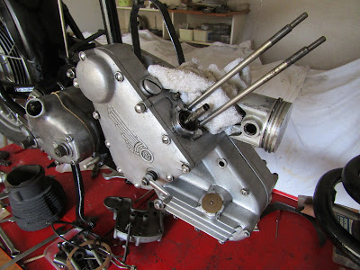
| 1954 unit to be used. |
This 600cc unit is dated 1954 and was running when I took it out of my rigid M100 as it was using oil although it had run happily for 15-20,000 miles. This engine has a single port head so I shall stick with that. When I first built this unit I fitted a new original Hepolite piston in a standard sized bore but the piston is set slightly to the timing side. A 0.032” feeler gauge will pass down the drive side of the piston with virtually no gap on the timing side. This suggests the conrod is slightly bent as is confirmed by the signs of blow-by on the drive side of the piston. The bigend and mains feel fine so I gave the rod a tweak to centralise the +0.040” piston in the barrel from the scrap engine. Then at least part of the old engine will run in the rebuilt bike.
 |
| Timing side. little blow-by. |
 |
Drive side, more blowby.
|
The original barrel was rusty on the outside with some paint still adhering but internally it looked ok with no lip at the top. The iron barrel was derusted in the electrolysis tank, dried off and sprayed with heat resistant paint. Internally a hone was run through to break the glaze from the old rings. The piston was cleaned, the ring grooves cleaned out and a set of new rings gapped and fitted.
I had a quick look in the timing chest and everything seemed fine, no wear on the cam and followers so the cover was put back on. The bottom end was then slipped into the frame; its much more manageable without the weight of the barrel and head.
 |
Engine in the frame.
|
With the engine inn the frame I could build up the transmission. I had found a new rear chain in the sidecar boot but when it was unrolled it fell into three pieces; some of the links had corroded to nothing. I selected another chain from my stock of bits and fitted that, followed by the inner primary chaincase which had been degreased and cleaned up. To hand I had a 25 tooth engine sprocket so I fitted that, lapping it onto the taper and using a new lock washer and a new disc in the sprocket nut, spreading the split pin so it couldn't slip out. The clutch went together easily with a new roller race and a new set of 24 rollers. The plain clutch plates that came with the bike were a bit distorted and the friction plates were well worn so again it was a case of diving into the parts store. There I found some flat plates and three friction plates with bonded on fibre linings so these went in. Finally I popped on a new primary chain and adjusted both chains.
 |
| Clutch and transmission sorted. |
The dynamo was found in the sidecar boot, rather rusty but apparently complete. I connected the two wires F and D together and put a voltmeter between that connection and earth on the body. A spin of the armature gave a kick on the meter indicating life so I ran it up on the lathe and got 14 volts. It was stripped and cleaned and the body repainted.
 |
| Cleaned and painted dynamo. |
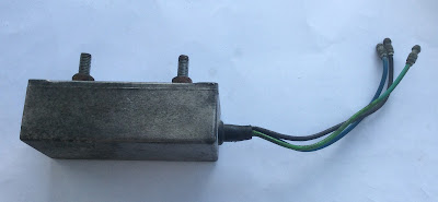
Attached to the frame of the bike at the regulator position was an alloy box which was not familiar to me but was identified on the Facebook group as a JG 6 to 12 volt convertor. Thanks chaps. I found some instructions on a BSA forum on the internet, wired it up and it all works after more than 20 years out in the weather.
 |
| JG convertor. |
Next stage to assemble the top end of the engine and tidy up a magneto. We are getting there slowly!
 |
| Wheels and engine in place. |


Aw! I wanted you to split the crankcase so I could get an idea of what to expect when I do mine. Im saving that for some winter entertainment. Setting up the top end willbe interesting though. Good work, Laurie.
ReplyDeleteSteve
It’s all in my Engine Manual Steve, I couldn’t see much point in stripping the bottom end when it was running well when I took it from my rigid, just using oil. Similarly details for assembling the top end are all in the book.
ReplyDelete