Now that I know it runs I can finish the bike off.
First the toolboxes. You may recall that both of these were rotted out at the bottom but P&M used the same box on each side of the machine with one mounted upside down relative to the other. This gave the possibility of joining the two good halves to make one box. So I set to with the grinder, mig welder, filler and paint and to my surprise ended up with, to me at least, an acceptable result.
The toolboxes as taken off the bike.
Two into one DOES go!
Finished with new knob.
Left hand toolbox remade from two.
The second box I bought from Ralph Eborn, having sold it to him some years ago. This was already painted and just needed touching up after filling a few spare holes and redrilling for the mounting bolts. So now we have a full complement of tool boxes.
Right hand box bought in.
The wiring loom and lights were fitted to the bike but gave some problems as I struggled to get the tail light to work. Eventually I realised that a small brass link in the switch was missing. Eventually all was well and the lights and horn functioned satisfactorily. The JG unit was mounted on new rubber mounts and bolted to the lugs under the saddle provided for the original regulator. Earth leads were run from this unit and the dynamo directly to the drilling in the frame under the saddle where earth leads from the lights and battery were also attached. I always provide earth wires from all the electrical items back to the frame rather than rely on current return through head bearings and painted surfaces. A check on the charging system must wait until another start-up.
JG unit on rubber mounts.
I had fitted a temporary exhaust for the start-up using a rechromed pipe and an old silencer. The pipe needed adjustment so I altered the flange at the cylinder head end so that the pipe tucked neatly under the gearbox. The old silencer that I had found lurking in the sidecar was rusty but solid. This was of the demountable type so it was taken apart and the body parts derusted by electrolysis. This process also lifted off a lot of the remaining chrome. As it is so solid I shall get it rechromed and fit it to the bike. For now I have put back the battered old one which, although very dented, still has chrome on it.
Demounted silencer before rechroming.
The primary chaincase was complete but covered in white aluminium corrosion product. This was cleaned back to bare metal and fitted with new cork gaskets and stainless screws. The long screw that is threaded into the battery platform on the frame was especially made from stainless steel hexagonal bar. With the case in place the left hand footrest, rear brake lever, spring, brake rod and stop-light switch were fitted.
Primary drive and brake completed.
The air filter was complete although again white with corrosion. The mesh was rusty but a new one was to hand and the felt filter was cleaned and oiled before assembly and fitting. A piece of car radiator hose joins the filter to the carburetter mouth.
Air filter and Concentric carb.
The seat base was painted and the seat reassembled using the old foam and cover; the latter being cleaned of old paint splashes using acetone. A small hole was covered by a patch glued to the underside.
Seat cover cleaned and refitted.
The original fuel tank was beyond repair. I had picked up another badly damaged one at the National Rally with the idea of making one from twoà la toolbox but that is probably beyond my skill level. Instead I decided to use a spare tank that I had once used on my rigid. It is the same shape as the scrap one that came with this bike. The original plastic badges on the wreck had gone milky but I have a pair of those tucked away somewhere along with the backing rubbers. This tank I lined with Por-15 ethanol proof sealer, respayed, lacquered and applied the Redwing transfer, an original varnish on type.
Redwing transfer, varnish-on type.
Resprayed tank.
The taps were cleaned and fitted with new plastic 'corks' cut from plastic wine bottle stoppers. These don't dry out and seal well though the thickness has to be adjusted by trial and error. Time is not a problem when drinking the wine.
Petrol tap "corks". 1. Plastic type wine "cork", 2. 15mm copper water pipe with sharpened end.
3. Copper pipe in the lathe rotated at slowest speed, "cork" pushed on, hand held, (wear gloves).
4. Push out cut section. 5. Cut off 2 slices about 0.18 inch thick, cut square with a sharp knife,
6. Punch centre hole, assemble tap. It should be tight but slide sweetly.
The gearbox was filled with one and a quarter pints of semi-fluid grease. This does not flow so is difficult to get it into the box. The answer is to heat it up to near boiling in a saucepan then pour it into the box through a funnel. Getting it out again is more difficult!
With a battery fitting the machine was hauled off the bench and taken outside for a photo shoot. All that is left to do is to ride it and shake it down.
Although the bottom end of the engine was beyond repair and I had substituted one that was lying around I felt that some of the old motor should live again. The piston in the old engine was a +40 slipper so this was cleaned up and a set of new rings found in the cupboard. The bore looked fine so this was honed to deglaze it and the barrel was derusted and painted. The head is a single port one from the replacement engine, the original being virtually scrap.
I found it easier to fit the piston and rings into the barrel on the bench, oiling the rings well and using finger pressure only to compress the rings into the cylinder as far as the gudgeon pin. I heated the piston with a hot air gun, offered it over the conrod and pushed in the pin. With a rag over the crankcase mouth to avoid dropping a circlip into the crankcase, the circlips went in and the cylinder was slid down onto the gasket which had been lightly smeared with sealant. Too much sealant can easily block the oil feed to the back of the piston. The head with ground-in valves was then put on and tightened down onto its copper gasket.
Cylinder and head in place.
Bare head.
The head was then built up sliding the pushrods down the pushrod tube and into the cups on the tappets. When inserting the rockers and their shafts I always turn the shafts so that the oil ways are not visible in the oil holes in the inlet rocker, but visible in those in the exhaust rocker. In theory this makes it more likely the oil jet on the inlet side will be more effective as oil is contained around the shaft, but the open holes and oil ways on the exhaust rocker will pick up oil splash to lubricate the exhaust shaft.
With the valves clearances adjusted so the tappets would rotate without play with the valves shut the engine was turned to open the exhaust valve whereupon the valve lifter arm in the rocker cover was slipped onto its peg and the cover bolted down onto a new gasket.
Completed engine.
A nicely rechromed exhaust pipe was bolted on but this doesn't fit too well, as usual, but this will do for now. The original carburetter is well corroded and the needle is rusty. Rather than attempt to clean this I found a brand new Concentric in the cupboard so jetted that to suit and fitted it to the manifold.
The old Monobloc, unretored.
New 32mm Amal Concentric carburetter,
The next step was to make sure the engine would run and for this I needed some sparks. No magneto came with the bike but in writing my Panther Heavyweight Cycle Parts Manual I had dismantled an old magneto and found its coils were ok. This I fitted with a new condenser and it gave good sparks on the bench. It was road tested by Phil Russell when he borrowed it to get home from the National Rally after his mag was flooded in the rain.
I also needed some controls as the handlebars and levers that came with the bike were totally shot. I painted some old bars and dug out all the necessary levers and clamps. None are perfect but they will do the job. Cables too came from the ever deeper cupboard. While working in this area I fitted the steering damper after polishing up the knob and painting the other bits.
Bars, controls and cables.
I filled the crankcase with straight 40 oil to the upper mark on the dipstick and rigged up a temporary fuel tank as the one I shall use is not yet ready. The gearbox is still empty but was oiled on assembly so should be ok for a short run. I was now ready to attempt a start. I flooded the carb, (no leaks!) set the ignition to half advance and closed the choke. After a priming swing or two with the valve lifter open, a proper swing produced a start; this petered out as the timing slipped, I'd forgotten to fully tighten the adjustable mag dog. After resetting the timing I had another go and away it went, filling the room with fumes. Just a short run was all that was required to show all was in order.
Try as I might, I can't get this video to run on the blog although it works on the design page. I'll put it on the Panther Facebook page instead although it is not that exciting. (ps Blow me down, it works on my mobile!)
Knowing we had life in the old girl I turned to the electrics. The dynamo and JG regulator were found to work ok as mentioned in the last post. I made up a wiring loom using the 1956 wiring diagram for cable colours. I have made a few of these and have a piece of timber with nails in strategic places so I can run the wires on that and tape them into their respective leads before cladding in shrink wrap. The dip-switch/horn-push loom was similarly treated.
Main loom.
Dip/horn loom.
I had a few problems in testing the loom using the original headlamp, a 12 volt sealed beam unit, and a battery. Firstly the ammeter wouldn't pass current so I found another one, then the dip switch fell on the stainless steel sink unit (yes, I was in the kitchen), shorted and blew the headlamp. Back then to an old prefocus type headlamp.
I had sprayed up the headlamp shell with all the other bits so fitted the original speedo which worked when spun on the lathe. I had taken out the Panther head medallion when stripping the bike but, when I actually found it in the confines of the shed, I discovered that the aluminium surround was badly corroded. I managed to turn up a new one although it had to be slightly deeper than the original which is a very flimsy affair.
Original badge in new surround.
Headlamp shell complete.
The original horn worked when current was applied but was pretty shabby. A coat of paint and a rechromed bezel worked wonders. I sourced new rubber trim and grommets for the headlamp shroud.
Horn and headlamp shroud.
The original tail lamp was cleaned up, the metal part painted and rewired.
Original tail lamp.
On the final stretch now, just to fit the headlamp and wiring, chaincase, footrests, semi-fluid grease in the gearbox and odds and ends.
Progress has been a bit slow with a long break in France although I did get the wheels built. Since then I have stripped and rebuilt the brakes, fitted some tyres and put the wheels into the frame.
The alloy parts of the brakes were quite badly corroded and covered in white corrosion product but they cleaned up ok. The linings had plenty of meat on them so they were degreased and the brakes assembled. There are two pull-off springs in the full width hub, one behind the other. Fitting the inner one proved to be rather taxing but clipped into place eventually. The hub cover plates were similarly white with corrosion but also cleaned up well. Spindles and spacers had all been zinc plated so assembly was fairly quick.
Assembled rear hub.
Before and after hub cover plates.
Front wheel in.
Rear wheel in.
Now we come to the heart of the matter. As readers may recall the original engine from 1960 had been replaced by a 1951 unit but this had been left exposed to the elements for more than twenty years with the rocker box removed. Damage was extensive with corrosion both external and internal.
1951 engine as found
With the head badly rotted and the crankcase split by freezing water I stripped it down and found a +0.040" bore in good condition with a slipper piston, standard fitment for 1951. As most of the rest of the motor was beyond salvage I turned to an engine which has sat under my bench for some years.
1954 unit to be used.
This 600cc unit is dated 1954 and was running when I took it out of my rigid M100 as it was using oil although it had run happily for 15-20,000 miles. This engine has a single port head so I shall stick with that. When I first built this unit I fitted a new original Hepolite piston in a standard sized bore but the piston is set slightly to the timing side. A 0.032” feeler gauge will pass down the drive side of the piston with virtually no gap on the timing side. This suggests the conrod is slightly bent as is confirmed by the signs of blow-by on the drive side of the piston. The bigend and mains feel fine so I gave the rod a tweak to centralise the +0.040” piston in the barrel from the scrap engine. Then at least part of the old engine will run in the rebuilt bike.
Timing side. little blow-by.
Drive side, more blowby.
The original barrel was rusty on the outside with some paint still adhering but internally it looked ok with no lip at the top. The iron barrel was derusted in the electrolysis tank, dried off and sprayed with heat resistant paint. Internally a hone was run through to break the glaze from the old rings. The piston was cleaned, the ring grooves cleaned out and a set of new rings gapped and fitted.
I had a quick look in the timing chest and everything seemed fine, no wear on the cam and followers so the cover was put back on. The bottom end was then slipped into the frame; its much more manageable without the weight of the barrel and head.
Engine in the frame.
With the engine inn the frame I could build up the transmission. I had found a new rear chain in the sidecar boot but when it was unrolled it fell into three pieces; some of the links had corroded to nothing. I selected another chain from my stock of bits and fitted that, followed by the inner primary chaincase which had been degreased and cleaned up. To hand I had a 25 tooth engine sprocket so I fitted that, lapping it onto the taper and using a new lock washer and a new disc in the sprocket nut, spreading the split pin so it couldn't slip out. The clutch went together easily with a new roller race and a new set of 24 rollers. The plain clutch plates that came with the bike were a bit distorted and the friction plates were well worn so again it was a case of diving into the parts store. There I found some flat plates and three friction plates with bonded on fibre linings so these went in. Finally I popped on a new primary chain and adjusted both chains.
Clutch and transmission sorted.
The dynamo was found in the sidecar boot, rather rusty but apparently complete. I connected the two wires F and D together and put a voltmeter between that connection and earth on the body. A spin of the armature gave a kick on the meter indicating life so I ran it up on the lathe and got 14 volts. It was stripped and cleaned and the body repainted.
Cleaned and painted dynamo.
Attached to the frame of the bike at the regulator position was an alloy box which was not familiar to me but was identified on the Facebook group as a JG 6 to 12 volt convertor. Thanks chaps. I found some instructions on a BSA forum on the internet, wired it up and it all works after more than 20 years out in the weather.
JG convertor.
Next stage to assemble the top end of the engine and tidy up a magneto. We are getting there slowly!
Readers of this blog may recall that the full width hub wheels of the Wreck were in a poor state. Half the front wheel had disappeared through corrosion, and the other three were badly rusted in the rim and spokes. Consequently the hubs were salvaged by cutting all the spokes and scrapping the rims.
The bearings and grease seals were then knocked out of the hubs. This job can be awkward as even with the tubular spacer between the bearings pushed to one side there is little of the inner race of the bearing showing to get a drift on. A drift with a mushroom head may help but I found that a 12mm Rawlbolt with the shells slightly turned down in the lathe would fit. Tightened hard into the tubular spacer gave something solid to hit. Handier people may be able to turn this into a bearing puller. All the bearings were washed out; most were in good condition and fit for further use.
All the alloy hubs were white with aluminium corrosion though two were found to have been powder coated. These were professionally blasted clean, the other two were cleaned up by hand, a time consuming and tedious job. The two really clean hubs were lacquered.
Hub before and after cleaning
The bearings were packed with LM grease.
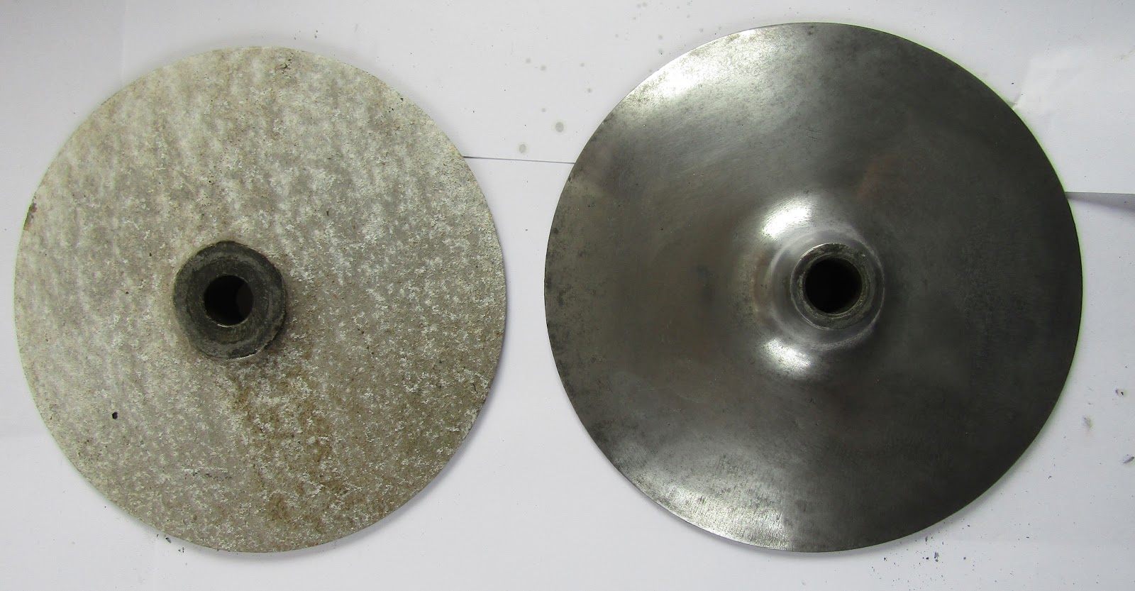
Hub with bearings, tube spacer, grease seals and ring spacer \(non-brake side)
Note, Meehanite (fine casr iron) brake surface.
Where new bearings are needed use those pregreased ones fitted with seals, these will last for ages without further greasing. I heated the hub centres to ease the fit and pushed a bearing onto its seat on the brake drum side. Turning the hub over the tube spacer was dropped in and the distance between the top of the spacer and the shoulder in the hub for the bearing outer was measured. This distance gives the maximum thickness for the shim under the bearing outer for the distance between the outer races of the two bearings must not exceed that between the inner races or the bearings will be crushed together when the wheel spindle is tightened. These hubs were selectively assembled at the factory as the castings vary even after machining. The tube spacer should feel tight between the bearings and not rattle around. The grease seals were then tapped into place.
Years ago when I rebuilt my 120 I had new rims and spokes fitted but kept the old rims at the back of the garage. These were dragged out and generally found to be sound so were cleaned of surface rust and loose chrome and painted silver with a lacquer top coat. I had boxes of spokes to hand so two sets were zinc plated. I then set about rebuilding the four wheels.
These wheels have 40 short spokes all of the same length and they cross once only so are easy to lace. I kept a complete wheel alongside as a reference. The inner spokes are fitted to the brake side first, then the wheel is turned over to fit the inner spokes on the second side. The outer spokes are then fitted to both sides.
assembled wheel ready for truing.
Using a wheel spindle I mounted the wheel on an old swinging arm and adjusted the spokes so that the wheel ran true radially and laterally with the rim central to the hub; there is no offset with these wheels. I aimed for a tolerance of 3/32 of an inch radially and 1/16 inch laterally. This can take ages and it is hard to achieve the given tolerances as many rims seem to have a kink at the weld. Finally all spokes were taken to an equal tension before grinding off any that protruded from the nipple.
As I've mentioned before the tinware, that is mudguards, headlamp, rear chainguard, toolboxes and fuel tank, was in a fairly poor state. The front mudguard was a non-Panther guard, holed with rust and chopped up when we loaded the van. The rear mudguard was a deeply valanced Panther type but upon dismantling it turned out to be a Panther front guard with a rusty extension bolted on to make up the length. The rear chainguard was the correct one although it had been repaired with the lower section replaced and fixed with pop-rivets. I decided to reuse this as is, just clean and paint. The toolboxes had both lost their lower third to the rust worm and were put to one side for later consideration. The headlamp was rusty on its lower half but recoverable, the fuel tank was beyond salvation. The rear number plate and the seat pan were both rusty and a little moth-eaten but usable.
Remains of the front guard.
Rear mudguard as taken off.
The fuel tank beyond repair
Seat, foam, pan and cover
The mudguards were stripped of paint and the numerous drilled holes and the odd rusted thin area were welded up and filled. The replacement back mudguard from my shed appears to be from a BSA as it had a recess at the bottom for the swinging arm. This was dressed out (for which read hit with a large hammer!) All the parts were rubbed down, sprayed with a primer filler then a couple of coats of top coat. I used a cutting compound and polish on this for a decent finish but went through to the primer on the rear mudguard so had to start again on that. Finish is not concours but looks adequate to me so the parts were bolted to the frame.
Front mudguard and headlamp shell.
Rear mudguard, number plate and chainguard.
Seat pan.
The replacement fuel tank is on its way and there is still work to do on the toolboxes but I shall turn to the engine next after a longish break during which I hope to lace up some wheels..
This Panther came with a set of leading link forks which look to be home made as the welding is pretty lumpy. This type of fork has been likened to fitting power steering to a motorcycle combination. Unfortunately in this case the pivot blocks on the leading link arm had completely rusted away so I had no idea where they should be. This meant a little research into the arcane laws of TRAIL.
The contact point of the front wheel of a motorcycle should trail behind the steering axis where it meets the ground to give a castor action. That is the wheel will return naturally to the straight ahead position after a turn, thus a bicycle can be ridden 'hands off' due to the trail of the wheel. This is positive trail, a lot of which makes for a stable machine at high speed but a sluggish one at low speed. Negative trail with the tyre contact in front of the steering axis leads to an unstable and very dangerous machine as the wheel wants to return to positive trail. Try pushing a bike backwards 'hands off.
Trail for the late Panther fork (Dimensions are approximate.)
On a motorcycle combination a lot of trail makes for very heavy steering giving a tiring ride with a lot of hard work so the trail should be reduced but remain positive. The front wheel needs to be moved forwards to reduce trail and backwards to increase it. P&M did this on their own forks and on Dowty forks by offsetting the axle from the centreline of the stanchion. Reversing the fork would change the trail but to a fairly minimal degree. I've ridden Panthers solo with the trail set in both positions, it seems to make little difference. Note that with late Panther forks you need to change the sliders to the other side so for solo use the brake is on the left hand side of the machine. Generally the bikes left the factory set for sidecar trail.
I set about measuring the trail on my bikes, not easy when it's all together. The late heavyweight Panther fork gives trails of 3.7" sidecar and 5.1" solo, Dowty forks, 2.2" and 3". My Douglas Dragonfly and Panther 10/3 have Earles forks, a form of leading link, with solo trail only 4" and 3.5" respectively. All measurements are approximate. Apparently Harleys have trail of 6"! The old bible 'Motorcycles and how to manage them,' suggests a positive trail of 1.5 inches for a sidecar outfit so I intend to aim for that but provide several mounting points to give an option for solo use. Drillings are provided for trails of 1.5”, 3” and 4”.
Setting out of leading links (Dimensions approximate.)
First I assembled the headstock bearings and fitted the yokes to the frame. The compound, braced, fork leg pair was put into the yokes, a tricky job as both legs have to go in together. I used two lengths of studding, nuts and washers to draw them into place. I put the rear wheel and a shock absorber into the swinging arm temporarily and adjusted the scissor table to give the correct ride height at the front using a dimension obtained from my M120.
A length of steel rod was passed through the crown nut and down the headstock stem to touch the bench. It was centralised in the bottom yoke by a drilled wine cork, (of course the wine had to be drunk first!) This gave the position of the steering axis at road level and the bench was marked accordingly.
Steel rod giving steering axis.
I fitted the original front shocks fully extended to their lugs and jacked the leading link up to contact my new saddles. This gave the original setting out more or less and gave a trail of about 2.5 inches. To move the wheel forward to a trail of 1.5 inches I had to disconnect the shocks to avoid the angle of the link changing. For solo trail the wheel is moved backwards so that the shocks are then too long when fitted between the welded lugs.
Original set up. approximate. (Saddles not fixed at this stage.)
My main concern, apart from whether the bike handles ok or not, is that in the maximum trail position the back of the link may foul the exhaust pipe. I've taken a check dimension of my other heavyweight and it is going to be tight.
The prepared saddles and bolts were tacked in position to the link and the whole assembly was fitted to the fork legs to check the setting out before they were fully welded in place. The welding was done professionally as I don't trust my own; a failure here is not to be contemplated.
Saddles located and tacked in place.
As mentioned above this setting out is different to that originally fitted so the shock absorbers will not fit between the lugs provided; these are welded to the fork legs and the link. The top ones were cut off and some sidecar clamps were prepared with new bolts and shims to provide adjustable top fittings to the shocks. Time will tell if the trail is correct!
Upper clamp fittings
The shocks were cleaned up and painted and the springs plated. the lower rubbers looked ok but the upper ones were replaced.
Front shocks cleaned up and plated.
The fork was assembled using new stainless bolts and self-locking nuts. I have checked the fit of the mudguard and it is clear that the setting for maximum (solo) trail will need to have a different or modified mudguard, if indeed the rear of the fork will clear the exhaust pipe. I used the central hole for assembly as I shall run the bike solo at first while I prepare the sidecar chassis. The first ride could be quite interesting!


